
How to Solve Surface Finish Issues in CNC Milling
In precision CNC milling, poor surface finish is one of the most common complaints I hear from engineers and machinists. This guide shows you exactly how to diagnose and fix surface roughness problems — step by step.
I’ve spent over 10 years programming and optimizing CNC mills. Today I’ll share the practical solutions that consistently deliver Ra 0.4 μm (16 μin) or better on aluminum, steel, and stainless — without expensive post-processing.
Understanding Surface Roughness Standards (Ra and Rz)
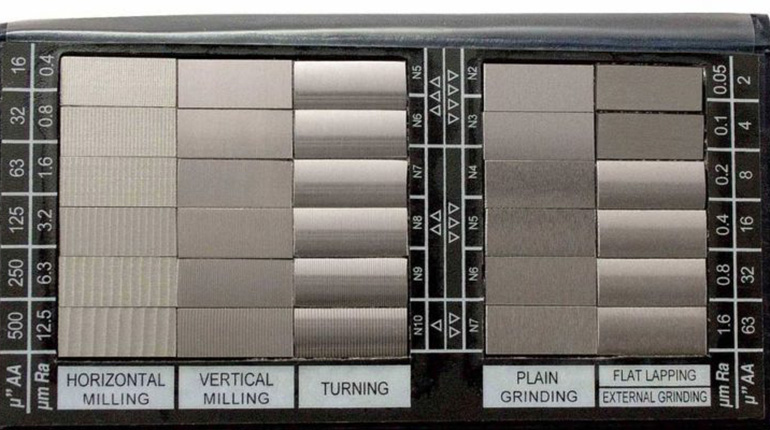
Ra (arithmetical mean roughness) is the most quoted value. It measures the average deviation from the mean line.
Rz (maximum height of profile) captures peak-to-valley distance and is 4–7× higher than Ra in typical milled surfaces.
Why Surface Finish Matters in Precision Engineering
- Mating parts with Ra > 1.6 μm increase wear 200–300% (SKF bearing studies)
- Aerospace sealing surfaces often demand Ra ≤ 0.8 μm to prevent leaks
- Medical implants require Ra ≤ 0.4 μm for biocompatibility and fatigue resistance
- Cosmetic parts sell better when Ra ≤ 0.8 μm — customers literally feel the difference
5 Common Factors Affecting CNC Surface Finish
- Excessive chatter/vibration
- Wrong feed per tooth (chip load)
- Tool deflection
- Climb vs. conventional milling direction
- Poor chip evacuation and heat buildup
Fix these five and 90% of surface finish problems disappear.
Optimizing Feeds and Speeds to Eliminate Chatter

Chatter leaves wavy “record grooves” and destroys Ra.
The fix is simple: keep chip load consistent and natural frequency away from spindle harmonics.
Calculating the Ideal Chip Load
Rule of thumb I use every day:
Chip load (mm/tooth) = 0.5–1.5% of tool diameter for finishing
Example: 10 mm 4-flute end mill → 0.05–0.15 mm/tooth
Actual formula for 6061 aluminum, 10 mm 4-flute, 0.5 mm DOC finishing pass:
- Spindle: 18 000 rpm
- Feed rate: 3600–5400 mm/min (0.05–0.075 mm/tooth) Result: Ra 0.3–0.5 μm and zero chatter
Minimizing Tool Deflection and Vibration Issues
A 10 mm carbide end mill sticking out 50 mm deflects 5–8× more than at 25 mm.
Every 0.01 mm of deflection roughly doubles the Ra value.
Importance of Rigid Workholding
- Use hydraulic vises or zero-point systems instead of cheap toe clamps
- Keep overhang < 3× diameter for finishing passes
- Support long parts with steady rests or tailstock whenever possible
Climb Milling vs. Conventional Milling: Which is Better?
Climb milling (tool rotates with feed direction) gives 2–3× better surface finish because:
- Chip thickness starts thick and exits thin → less rubbing
- Downward force improves stability
Only use conventional milling when machine backlash > 0.02 mm or on very thin walls.
Choosing the Right Cutting Tools and Coatings
For mirror finishes in aluminum: polished flute + ZrN or DLC coating
For steel: variable helix + AlTiN or AlCrN
For stainless: 5–6 flute variable helix + nACo coating
Flute Count and Helix Angle Impact
- 2–3 flutes → best chip evacuation in aluminum (roughing)
- 4 flutes → good balance
- 5–7 flutes + 45° helix → smoothest finish in steel and stainless (less vibration)
Effective Chip Evacuation and Coolant Strategies
Re-cutting chips is the #1 cause of scratched surfaces.
Solutions that work:
- High-pressure through-tool coolant (70 bar)
- Air blast + mist for aluminum
- Trochoidal toolpaths with 5–8% stepover in pockets
- Peck drilling instead of full-depth drilling when finishing floors
Post-Processing Methods to Enhance Surface Quality
If you still not perfect:
- Light spring pass at 0.1 mm DOC, 0.02 mm/tooth, 25 000 rpm
- Ball-end mill “contour” pass parallel to surface
- Manual or robotic polishing (3M Trizact A6 → A3)
Achieve Superior Finishes with Standard Machining Services
At Standard Machining we routinely hit Ra 0.4 μm on 5-axis simultaneous parts using the exact strategies above — on standard Haas and DMG Mori machines, not exotic grinders. No secrets, just disciplined process control.
Conclusion
Master chip load, rigidity, climb milling, tool selection, and chip removal → mirror finishes become normal, not rare. Implement these changes and your rejection rate for surface finish will drop dramatically.
Ready to stop fighting surface finish issues? Contact Standard Machining for a free process review on your toughest part. We turn “impossible” Ra targets into daily production reality.
FAQs about CNC Milling Surface Finishes
What Ra can I expect from a standard 3-axis CNC mill?
With proper technique, Ra 0.8–1.6 μm in aluminum and Ra 1.6–3.2 μm in steel is normal. Optimized 5-axis and polished tools reach Ra 0.2–0.4 μm.
Why does my aluminum part look scratched after machining?
95% of the time it’s built-up edge or re-cut chips. Switch to polished flutes, sharper edges, and high-velocity air/mist.
Is spindle speed or feed rate more important for finish?
Feed per tooth is king. Too low → rubbing and work hardening. Too high → chatter. Get chip load right first, then fine-tune rpm.
Can coatings really improve surface finish?
Yes. Polished ZrN/DLC reduces aluminum adhesion by 70–90% and lowers Ra from ~1.6 μm to ~0.4 μm in the same conditions.
When should I consider hand polishing instead of machining better?
Only when Ra ≤ 0.2 μm is required for optical or extreme wear reasons. Otherwise, fix the machining parameters — it’s faster and cheaper.


Recent Posts

LET’S START WORK
TOGETHER
Please feel free to contact us. We will get back to you with 1-2 business days. Or just call us now.